

Size group 30/25
With transverse mounting holes: Ø 14 mm.
Stroke: 100, 150, 200, 250, 300 mm.
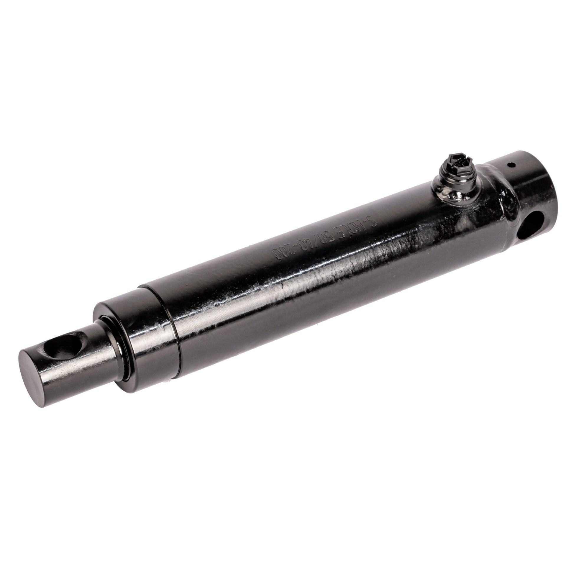
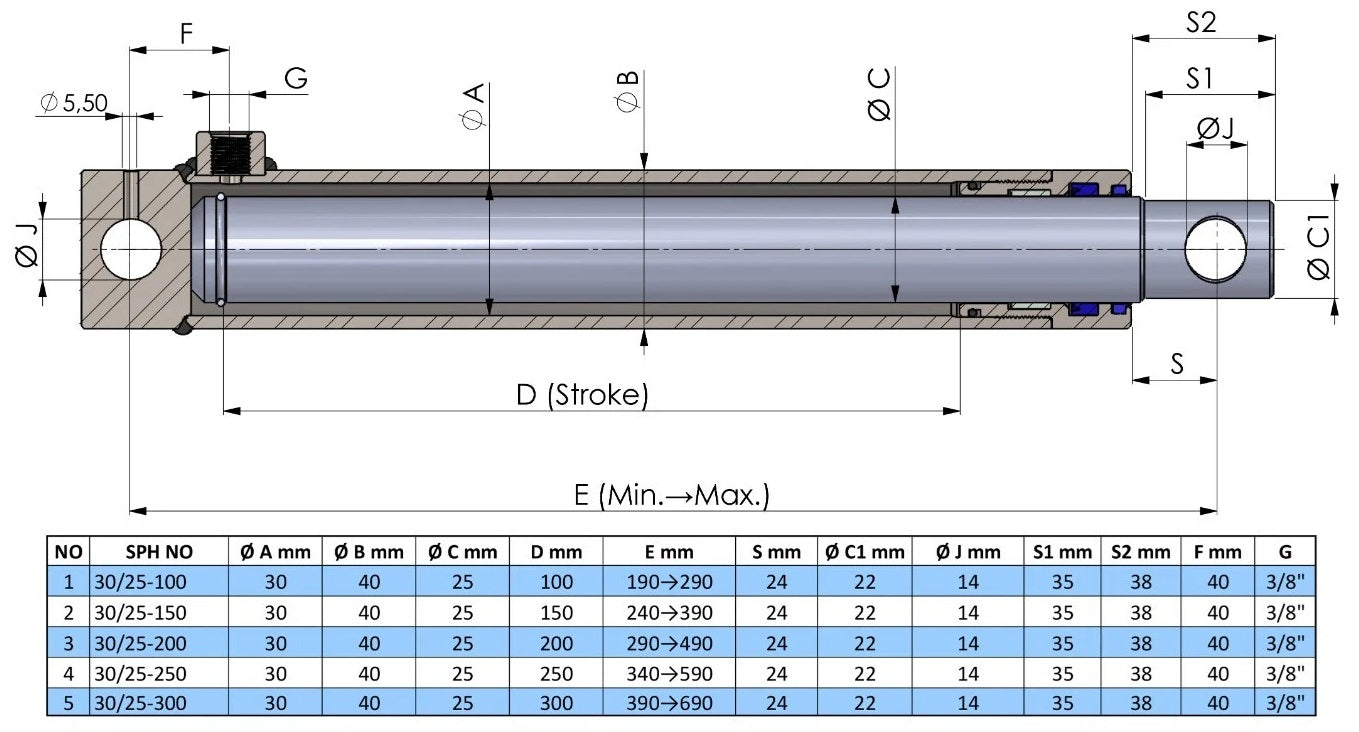
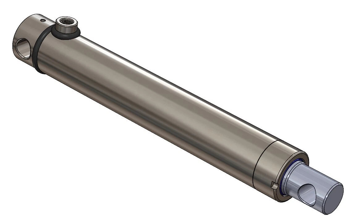

Hole 30/25-Stroke
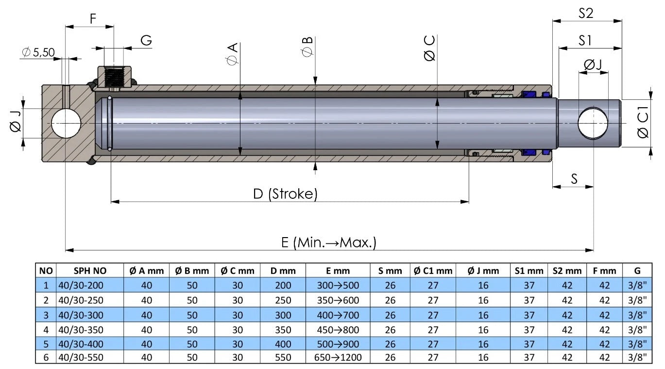

Hole 40/30-Stroke
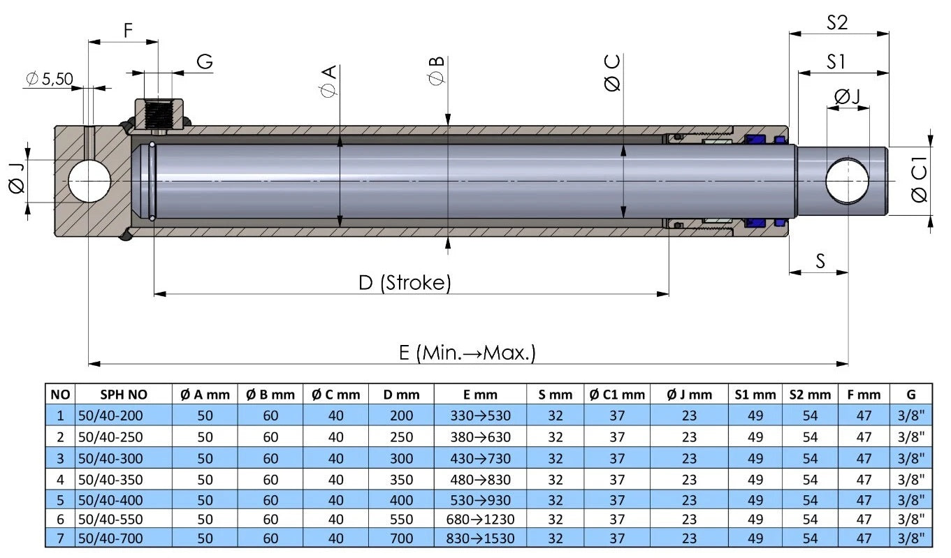

Hole 50/40-Stroke
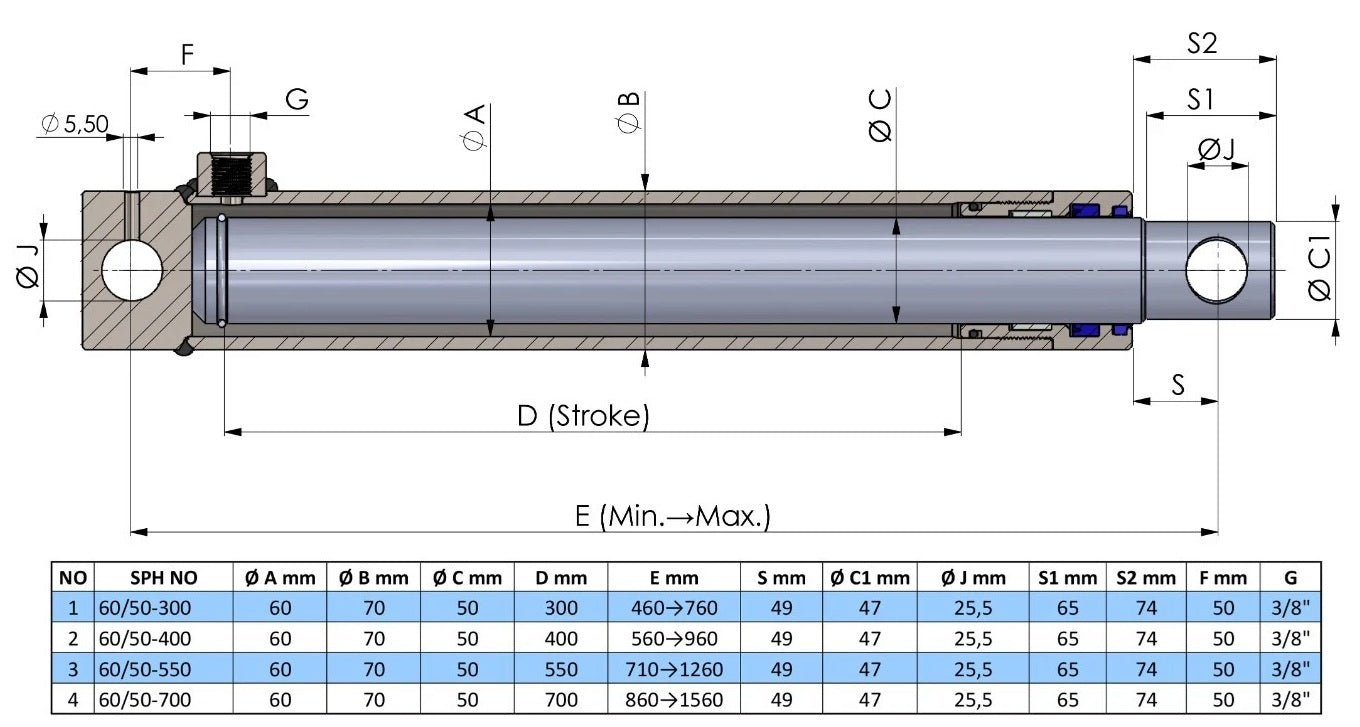

Hole 60/50-Stroke
A single-acting hydraulic cylinder with transverse mounting holes has a fixing hole at the base and in the rod end. Oil pressure extends the cylinder; the machine must provide the return movement. Choose from four metric size groups and 22 stroke variants, and compare the mounting and center-to-center length with your existing cylinder.
Measure the mounting-hole diameter and the distance between the hole centers. Check both the retracted and extended positions. The load, gravity or another external force from the machine must be able to retract the cylinder.
The size code 40/30 means a 40 mm bore and a 30 mm rod diameter. It does not specify the mounting-hole diameter. Stroke is the extension travel. Check installation space and load as well; do not select by the size code alone. All dimensions below are in millimetres.
With transverse mounting holes: Ø 14 mm.
Stroke: 100, 150, 200, 250, 300 mm.
With transverse mounting holes: Ø 16 mm.
Stroke: 200, 250, 300, 350, 400, 550 mm.
With transverse mounting holes: Ø 23 mm.
Stroke: 200, 250, 300, 350, 400, 550, 700 mm.
With transverse mounting holes: Ø 25.5 mm.
Stroke: 300, 400, 550, 700 mm.
All table dimensions are in millimeters. Retracted and extended lengths are measured between the centers of the mounting holes, as dimension E on the drawing. Stroke is the extension travel. Select an SPH code to open that product variant.
Once you know the size and stroke, open the relevant version and select the SPH code. Tables can be scrolled sideways on narrow screens.
The mounting pin passes through the hole in the cylinder end. Compare the hole diameter, space around the mounting, overall dimensions and alignment. Matching stroke alone does not establish interchangeability.
For the version with transverse mounting holes, the drawing length is measured between the centres of the mounting holes. For the standard version, it is the overall length from the rear face of the cylinder base to the rod tip. These are different measurements. Use the measuring points on the product drawing and check both the retracted and extended positions.
Standard — Single-acting hydraulic cylinders
The recommended working pressure for these cylinder groups is 180 bar; the maximum pressure is 250 bar. Also check stroke, mounting, alignment and load for your application. Maximum pressure alone does not determine whether a cylinder suits your machine.
Oil pressure extends these cylinders. Retraction requires the load, gravity or another external force from the machine. The installation must allow this return movement. If you need hydraulic force in both directions, compare the double-acting cylinders.
Single-acting hydraulic cylinders · All hydraulic cylinders
With a mounting hole at the base and in the rod end. Compare the hole diameter, mounting dimensions and centre-to-centre length with the machine mounting.
These cylinders are not hydraulically pulled back through a second oil port. The load, gravity or another external force from the machine must provide the return movement.
No. Size 40/30 means a 40 mm bore and a 30 mm rod diameter. The mounting hole for this size is 16 mm according to the drawing. Check these dimensions separately.
Measure from the center of one mounting hole to the center of the other. Check both retracted and extended lengths using the same measuring points as the drawing.
Send us a WhatsApp message with the required stroke, hole diameter and center-to-center lengths. Add a photo of the existing cylinder and machine mounting so we can compare the appropriate version.