

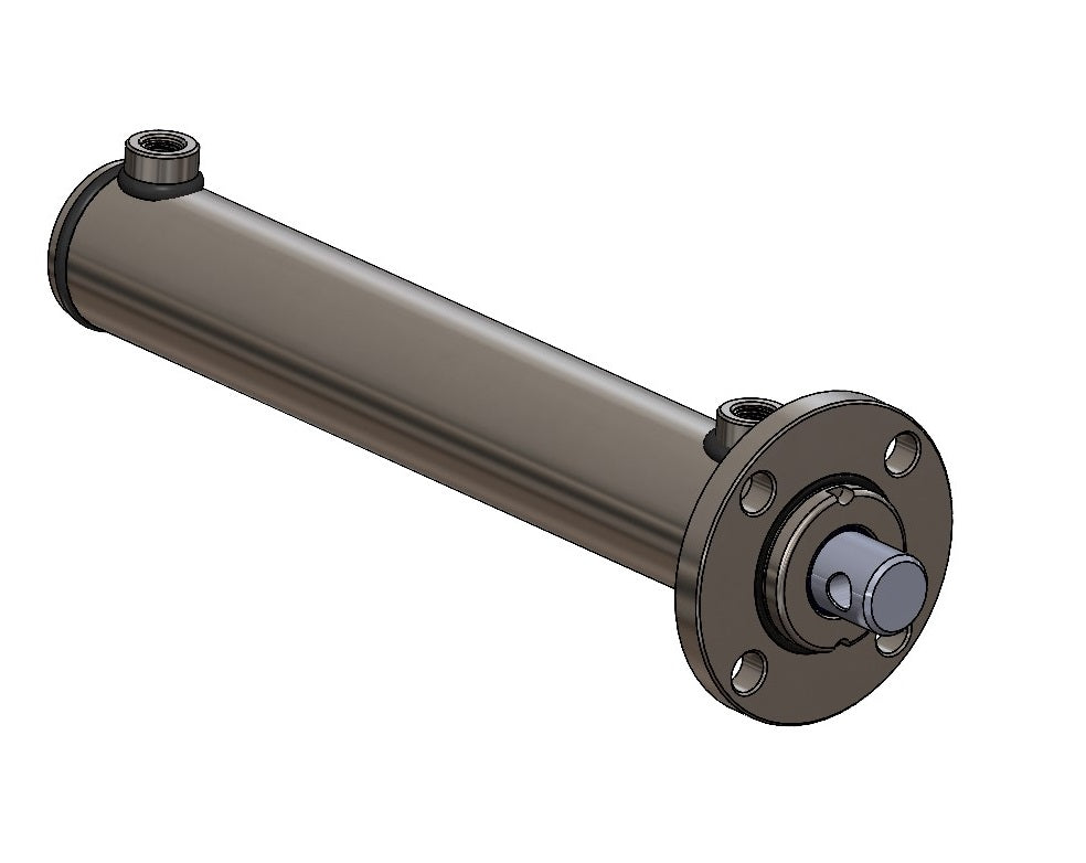
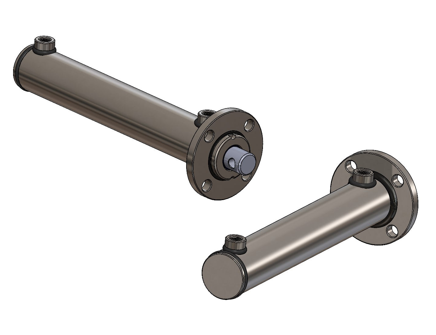

Double-acting hydraulic cylinders with front flange
A double-acting hydraulic cylinder with front flange is mounted to the structure by a flange at the rod end. Hydraulic pressure extends and retracts it. Check the flange and rod attachment first, then choose stroke and length.
80/50 with front flange: choose your stroke
This collection currently offers one size with five strokes: 300, 400, 500, 600 and 800 mm. The bore is the internal cylinder diameter.
View the 80/50 cylinder and choose your variant
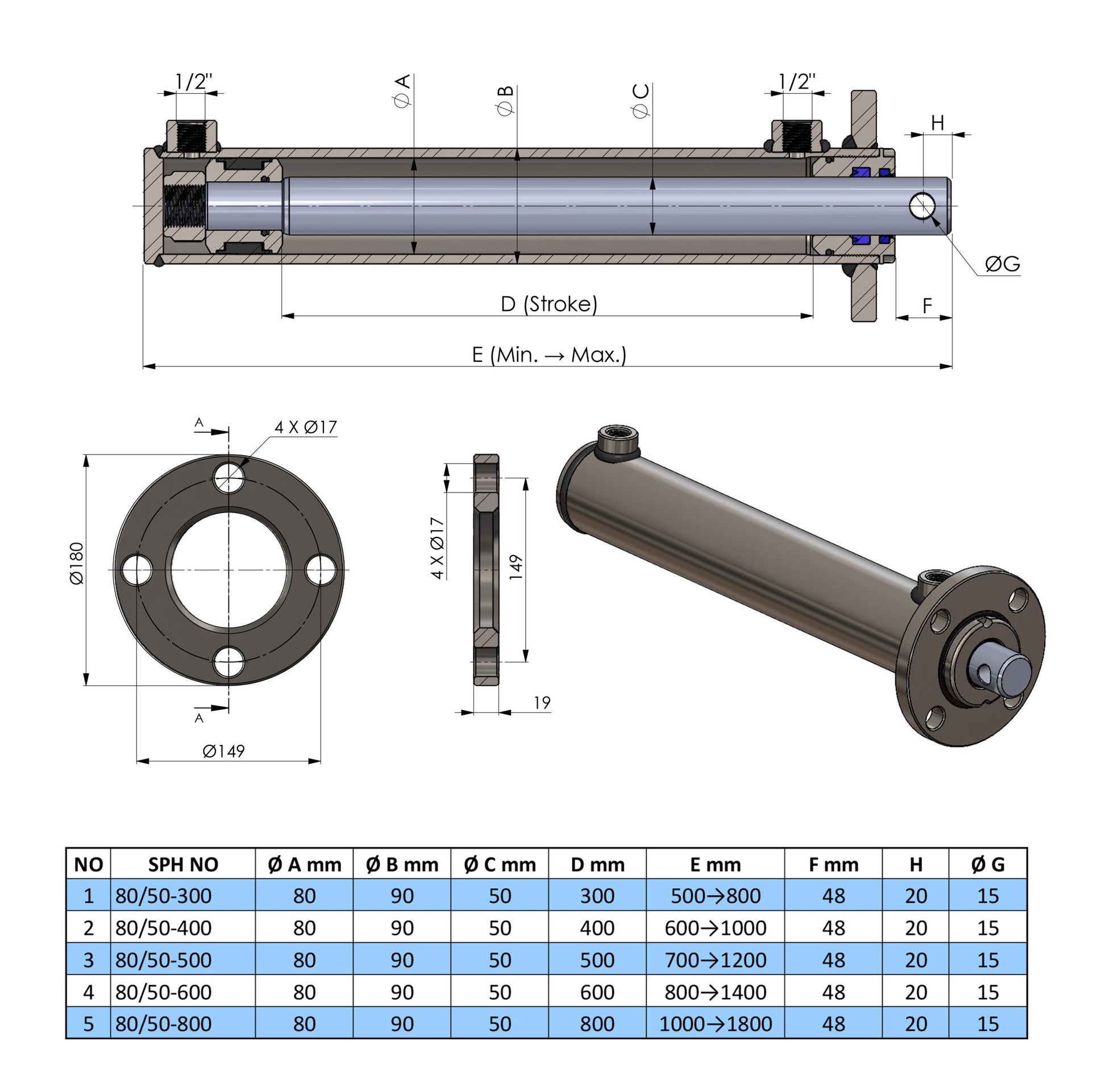
Compare stroke and length
All dimensions are in millimetres. Here, retracted and extended lengths run from the rear face of the cylinder base to the tip of the rod. Use the same measuring points on your existing cylinder. On narrow screens, scroll the table sideways.
| Part number | Stroke | Retracted length | Extended length |
|---|---|---|---|
| SPH340324 | 300 | 500 | 800 |
| SPH340325 | 400 | 600 | 1000 |
| SPH340326 | 500 | 700 | 1200 |
| SPH340327 | 600 | 800 | 1400 |
| SPH340328 | 800 | 1000 | 1800 |
Check the flange and rod attachment
- Flange diameter: 180 mm.
- Hole pattern: four 17 mm holes on a 149 mm pitch circle.
- Flange thickness: 19 mm.
- Rod cross-hole: 15 mm diameter; its centre is 20 mm from the rod tip.
Compare the complete hole pattern and flange position with the machine mounting. Check clearance behind the flange and around the rod. Choose suitable bolts, pins and retainers for the structure.
Choose a suitable replacement
- Mounting and alignment: check the front flange suits the structure and the rod can move in the required direction. Avoid side loads on the rod.
- Stroke and space: compare required movement and overall length at both end positions. Matching stroke does not automatically mean identical overall dimensions.
- Force and buckling: match bore, rod diameter, stroke and mounting to the required pushing and pulling forces. These differ at the same pressure. Pay attention to buckling with longer strokes.
- Hydraulic connections: compare the selected cylinder connections with your hoses, fittings and hydraulic system.
- Exact part: open the SPH link in the table and check the selected stroke and technical details before ordering.
Working pressure and maximum pressure
Recommended working pressure is 180 bar and maximum pressure is 250 bar. Allowable pressure also depends on buckling load and mounting. Do not automatically use the maximum as continuous working pressure.
Need a different mounting?
Compare Double-acting hydraulic cylinders, Clevis and Fork and Point. Choose a mounting that suits the structure and movement.
Help with replacement
Have the SPH code, mounting photos, flange hole pattern, rod attachment, stroke, both lengths and system pressure ready. Contact us via WhatsApp or browse Hydraulic Cylinders.
Frequently asked questions
Where is the front flange?
At the rod end, where the rod exits the cylinder. The flange attaches to a suitable mounting plate or structure.
What does 80/50 mean?
An 80 mm cylinder bore and a 50 mm rod diameter. It does not describe flange or mounting-hole diameter.
Are the table lengths centre-to-centre distances?
No. Here the length runs from the rear face of the cylinder base to the rod tip. Measure your existing cylinder the same way.
Do all front-flange cylinders fit the same mounting?
No. Compare flange diameter, hole pattern, thickness, rod attachment, flange position, stroke and overall dimensions. Load and system pressure must also suit the application.
Which strokes are available?
300, 400, 500, 600 and 800 mm. Each has its own SPH code. Select the code in the table to open that variant.