

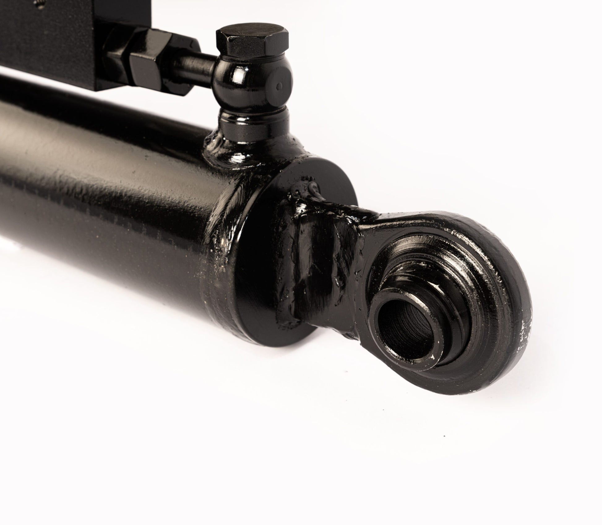
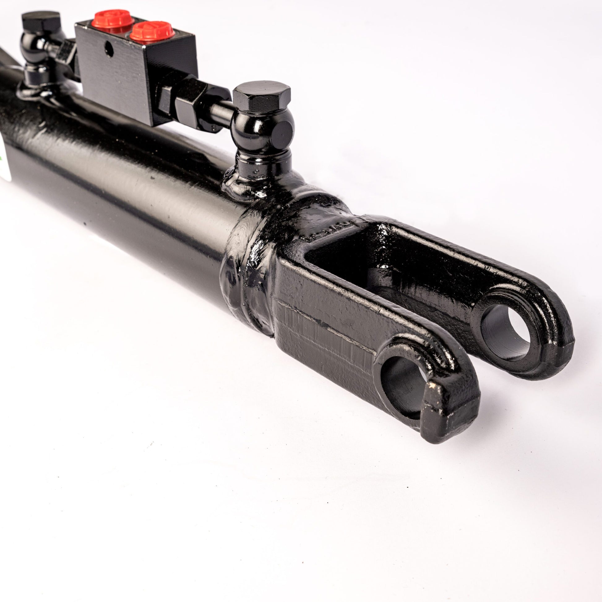
Hydraulic Lift Links
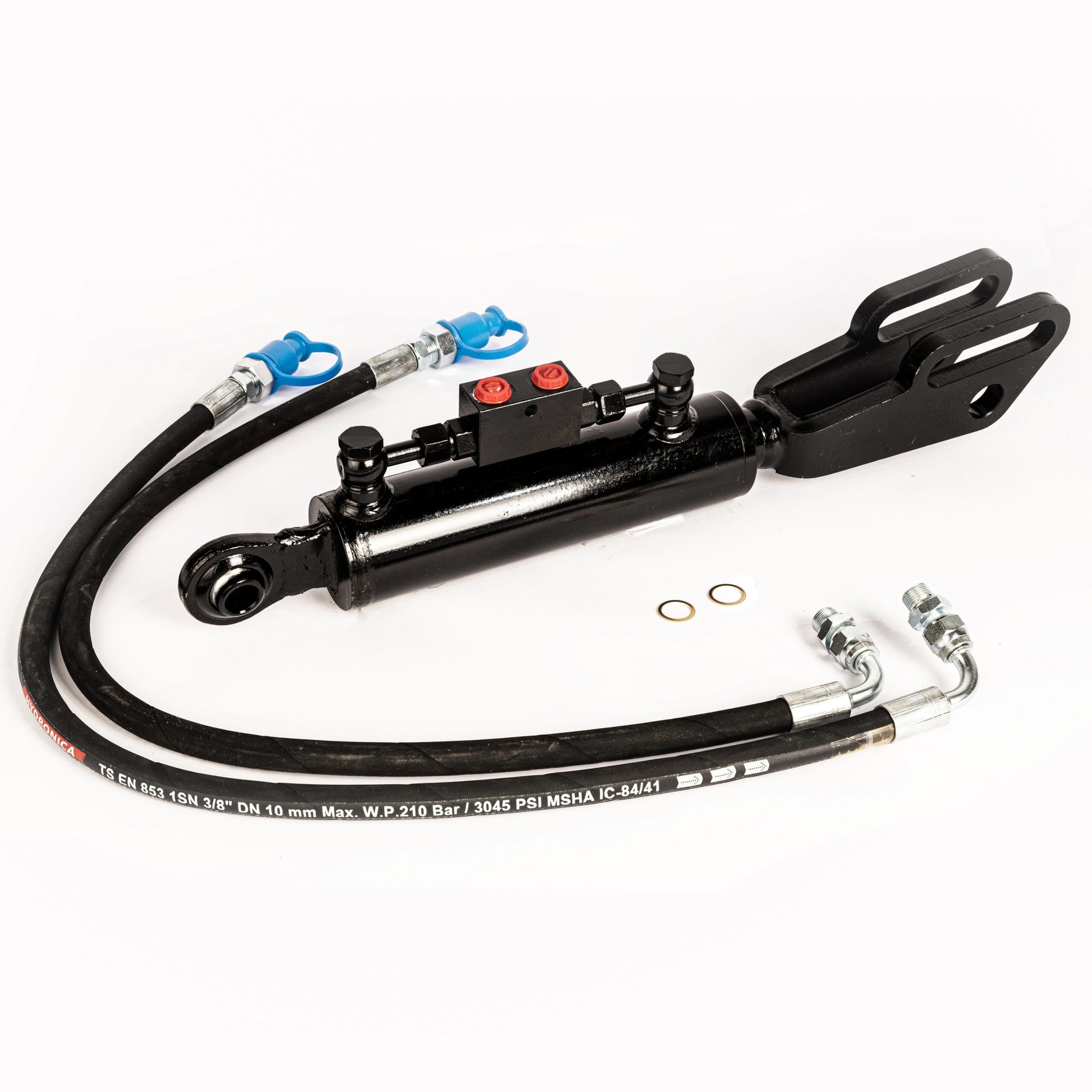
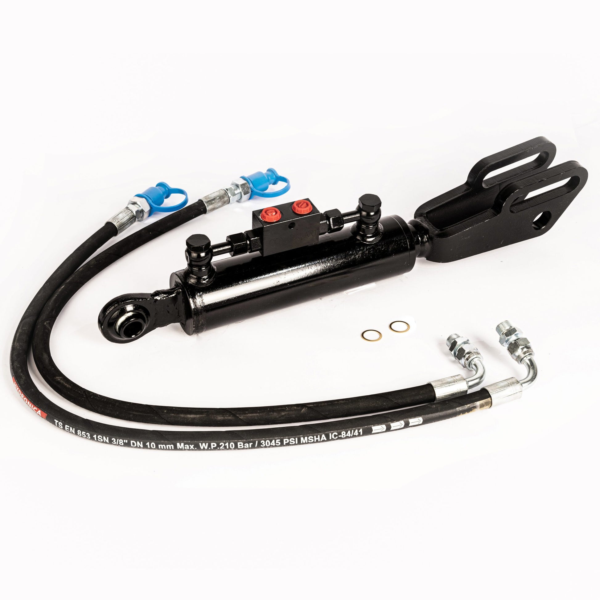
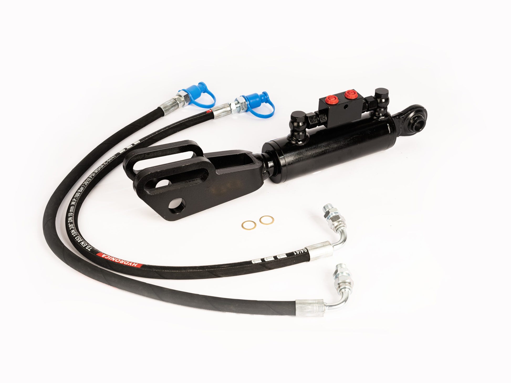
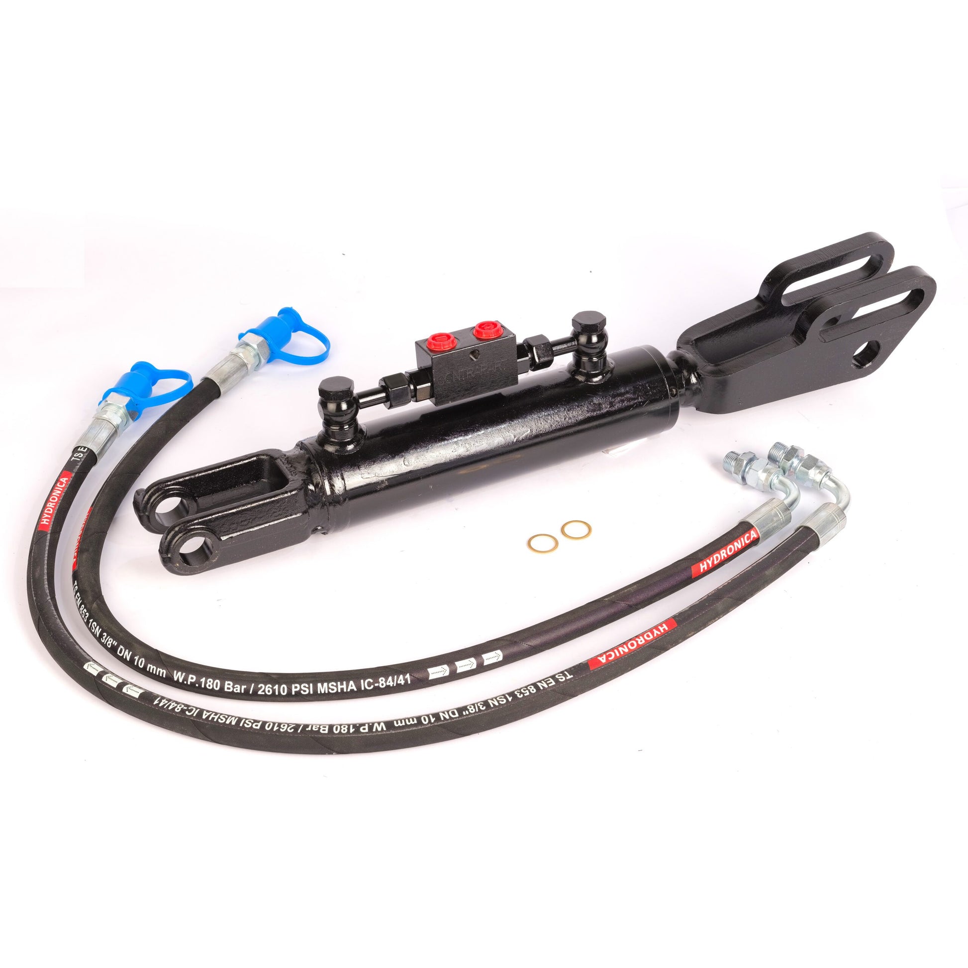
A hydraulic lift link adjusts the height of one lower link on the tractor’s three-point linkage. This lets you set the side-to-side tilt of the implement using the tractor hydraulics. Compare six hydraulic side links below by end fittings, retracted and extended length, and stroke.
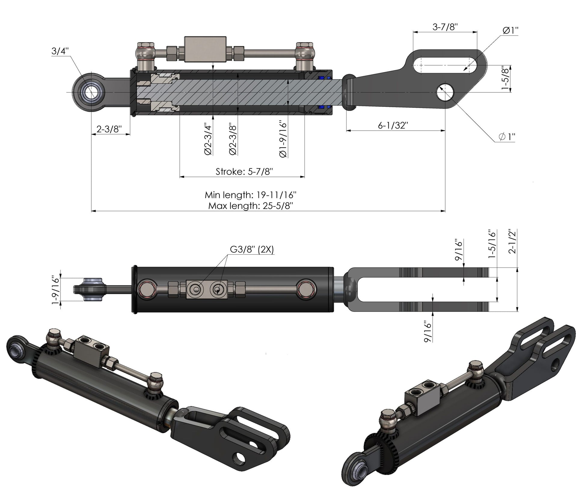
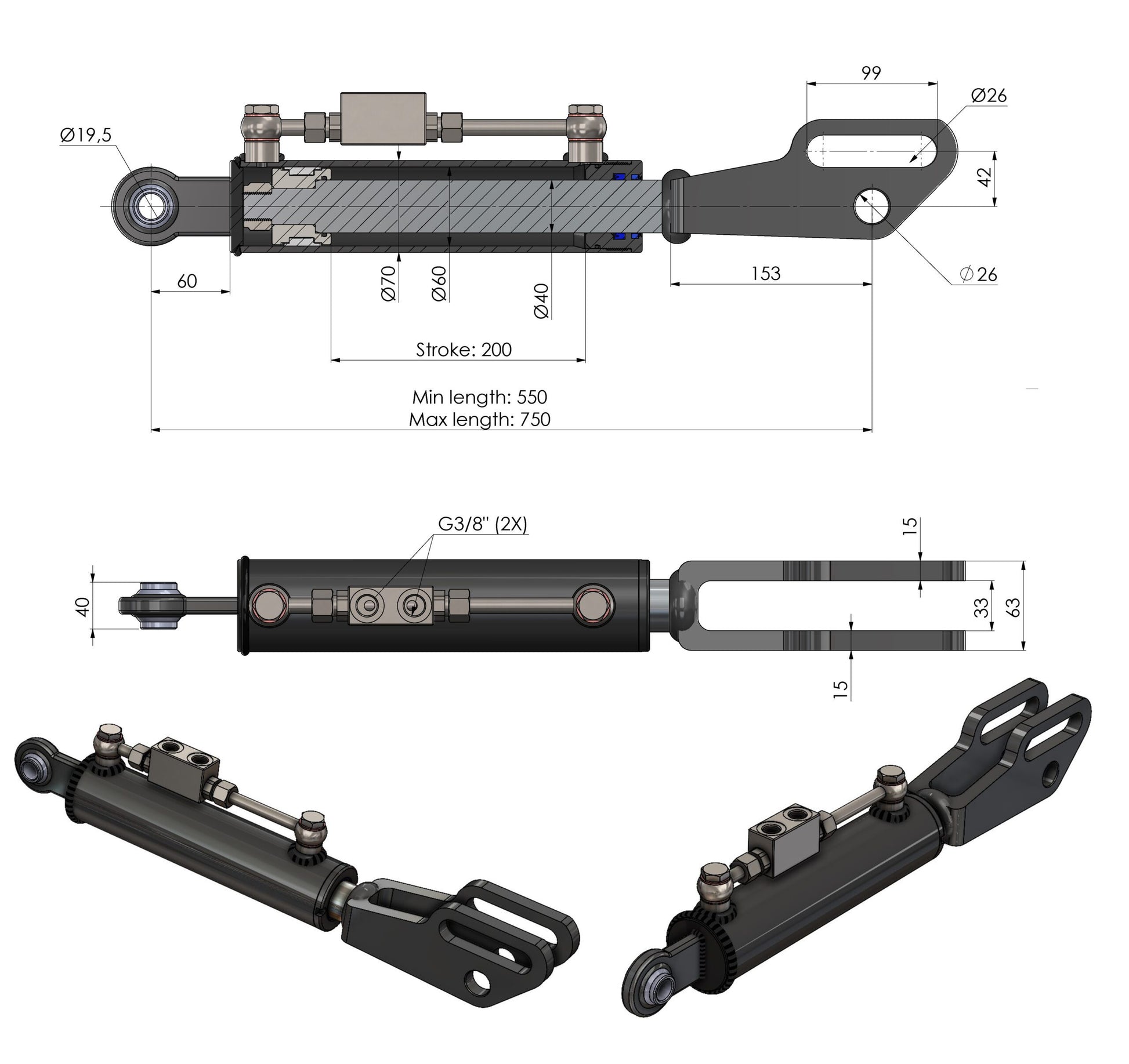
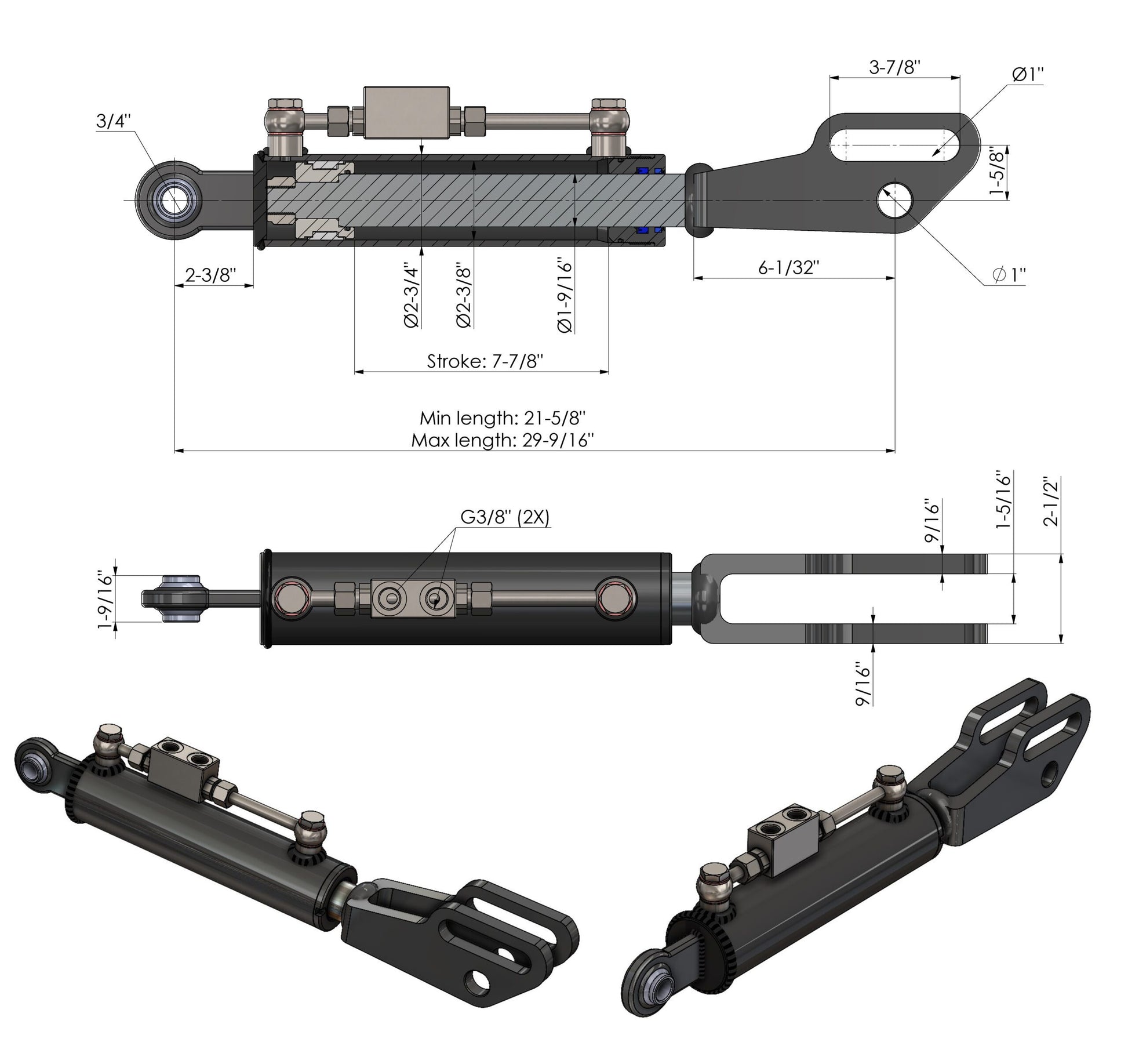
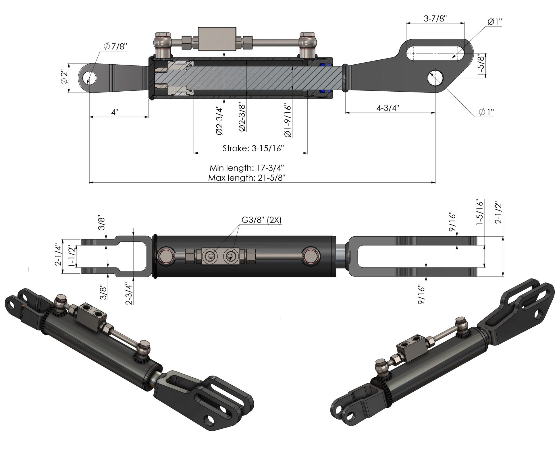
Choose the end fittings first, then the length range. Check both ends, hole diameters, clevis inside widths and installation clearance. The same length does not guarantee the same fit.
Which hydraulic lift link do you need?
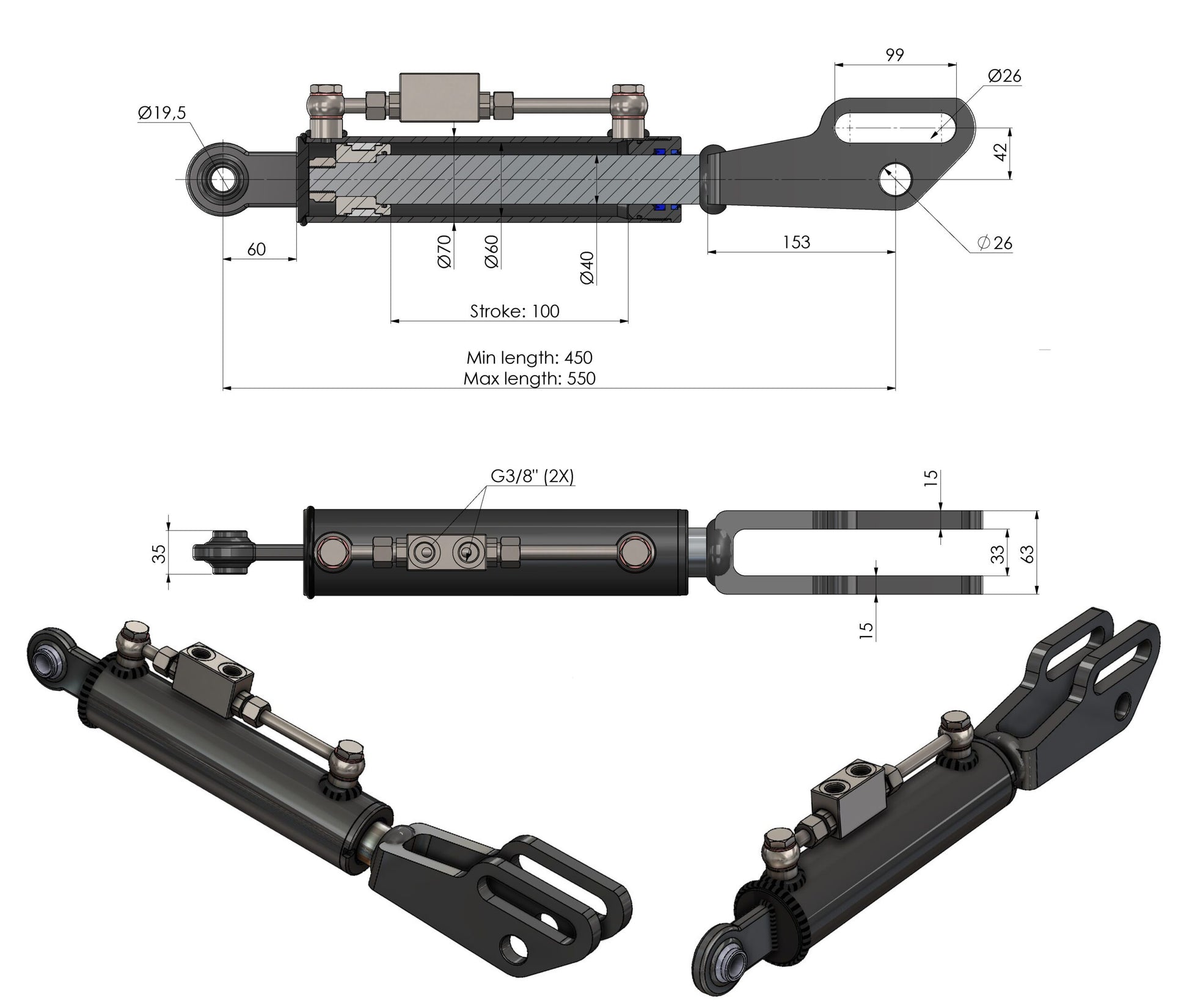
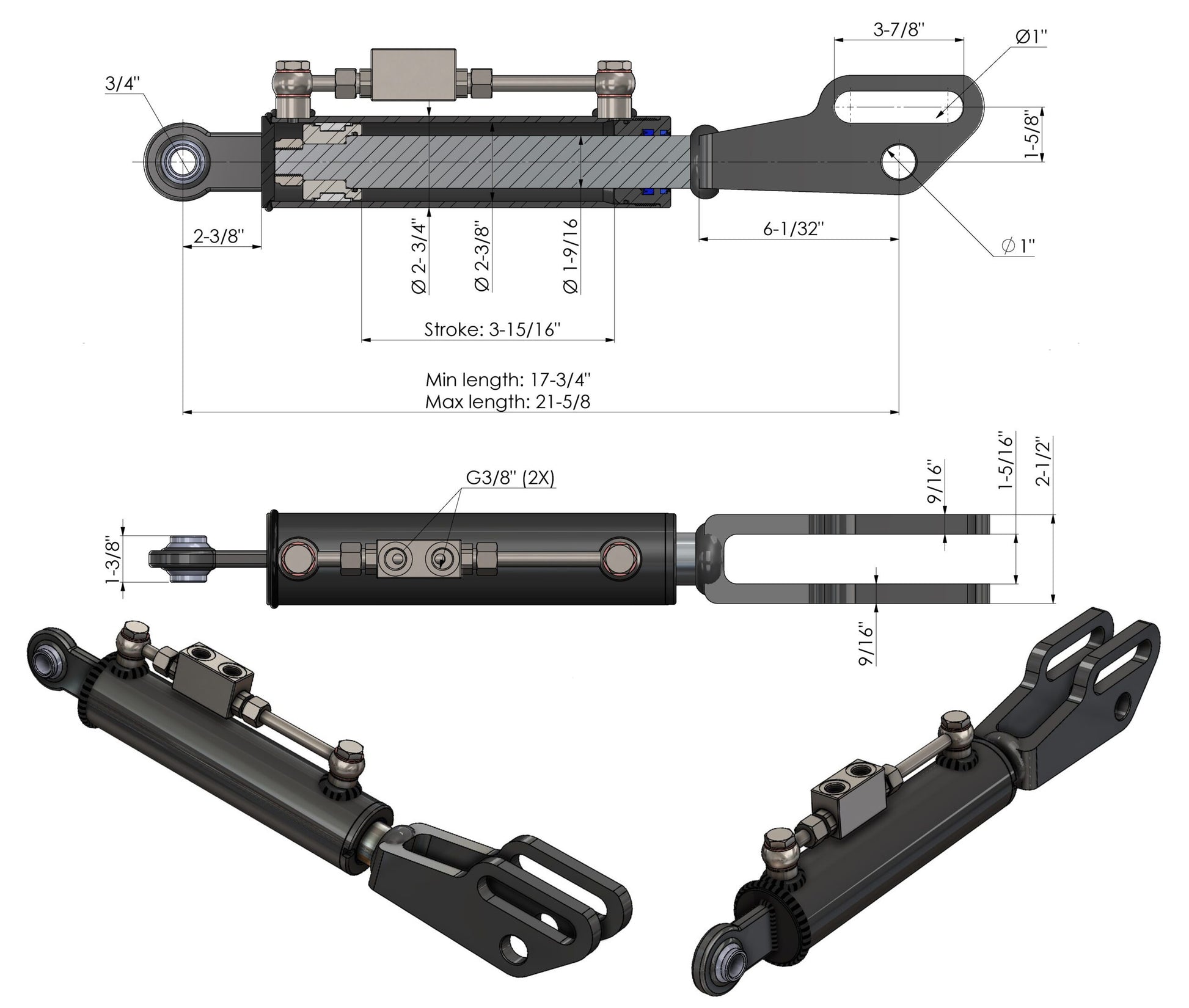
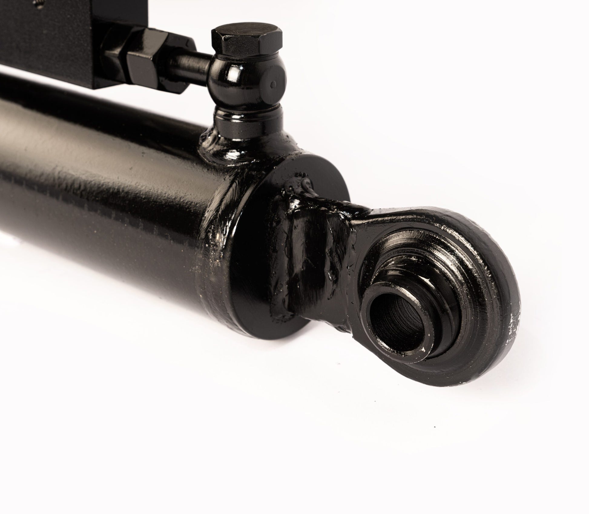
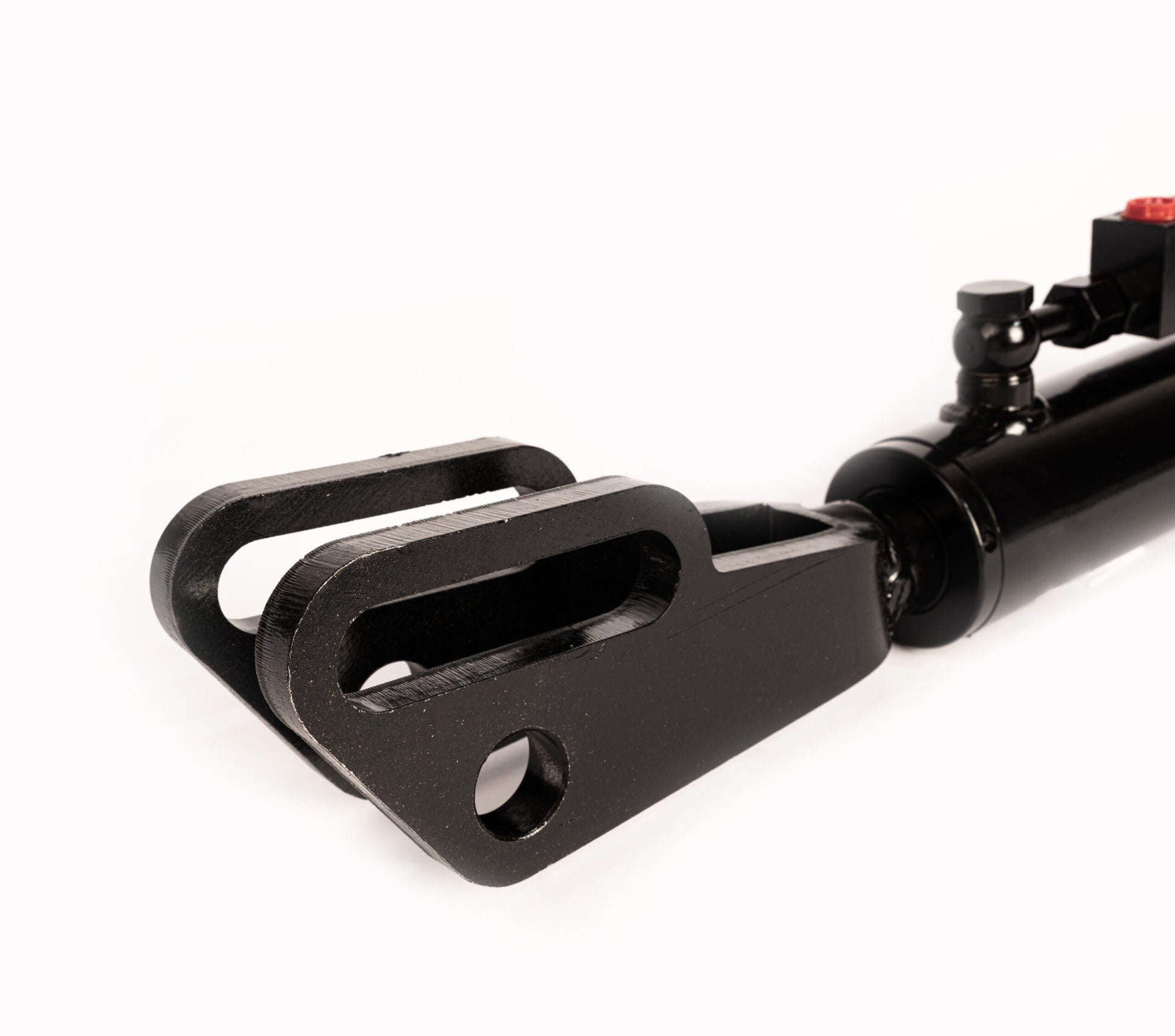
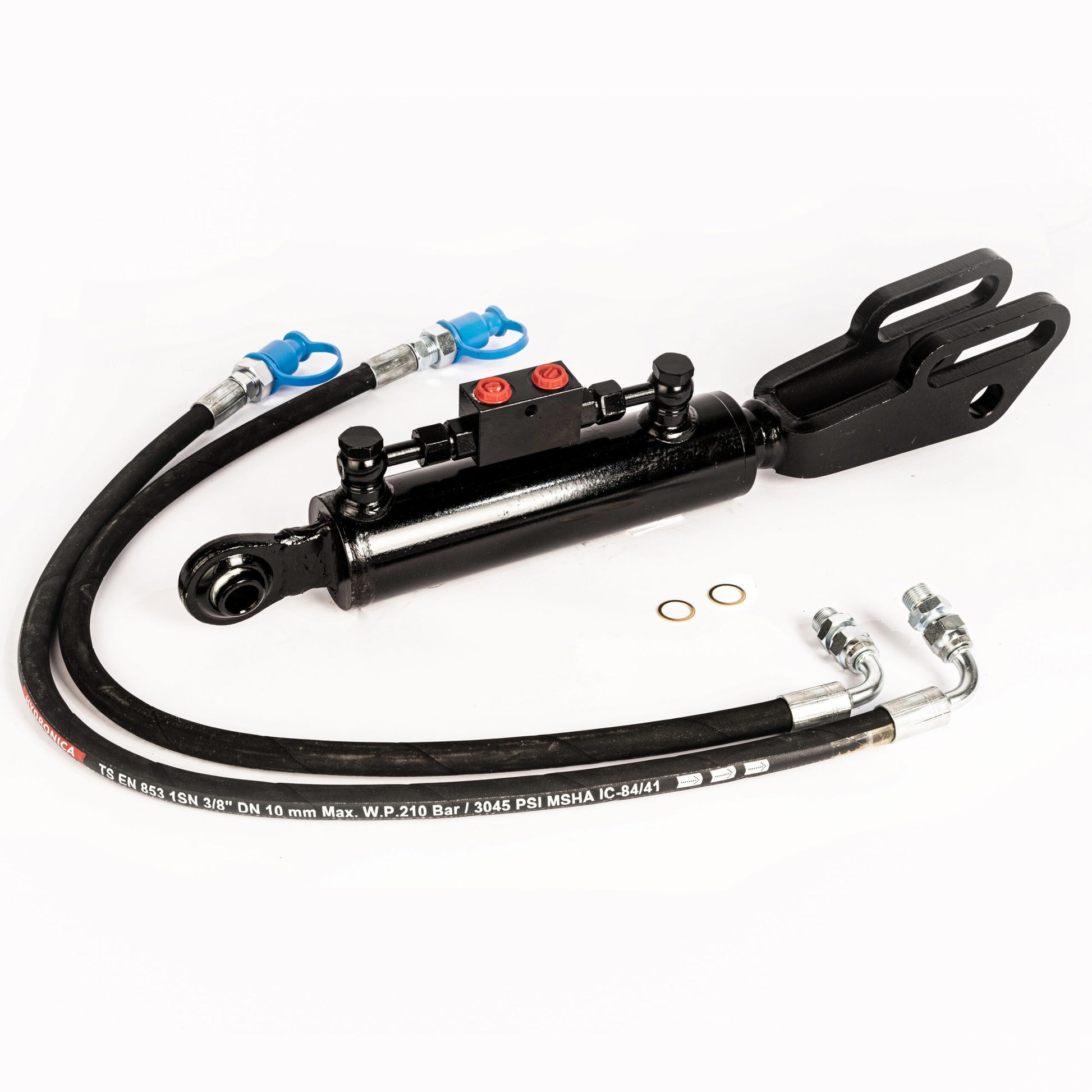
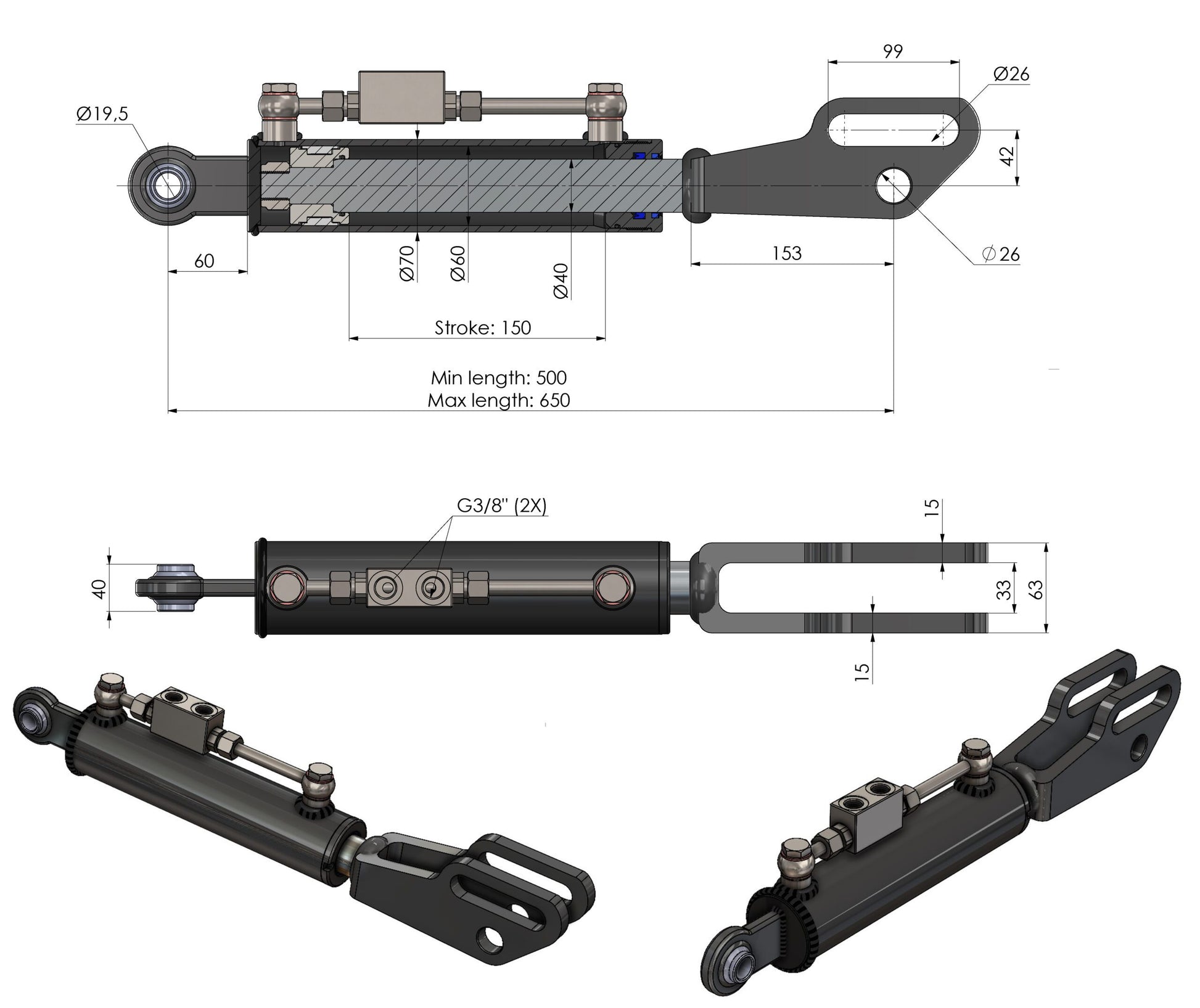
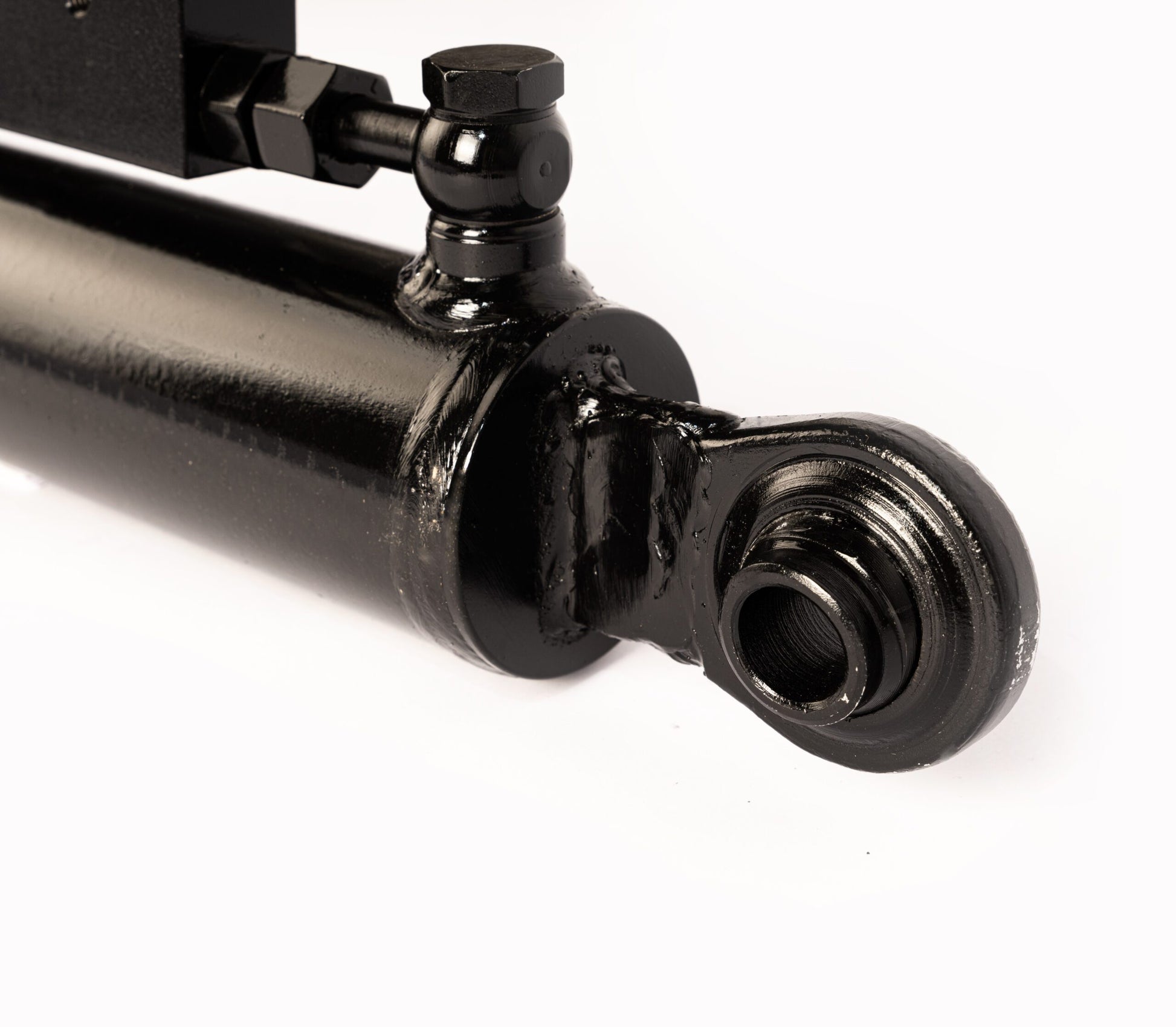
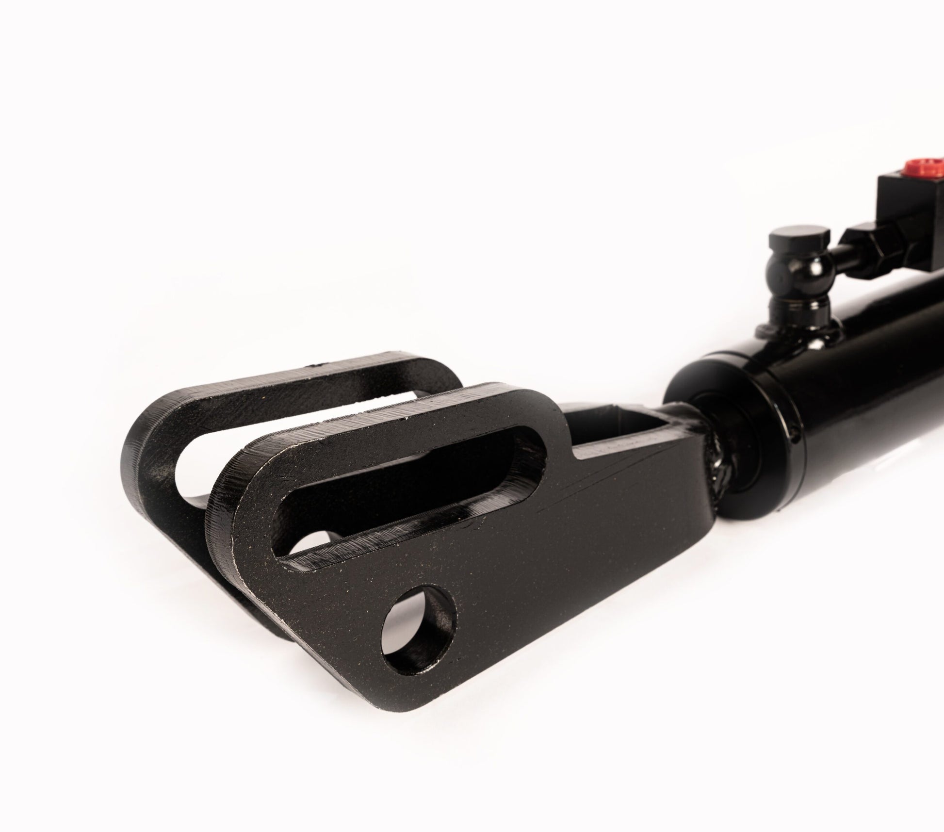
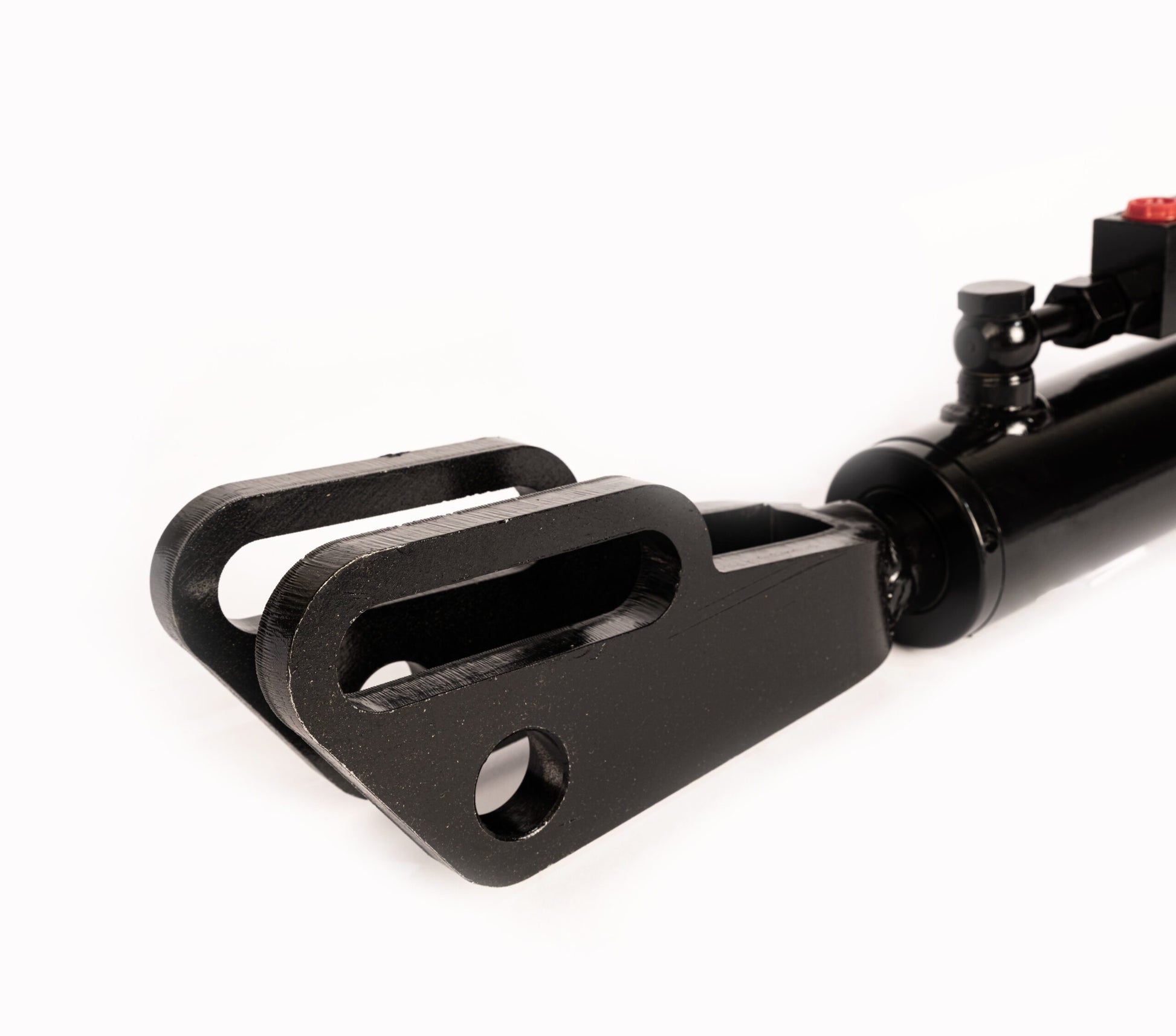
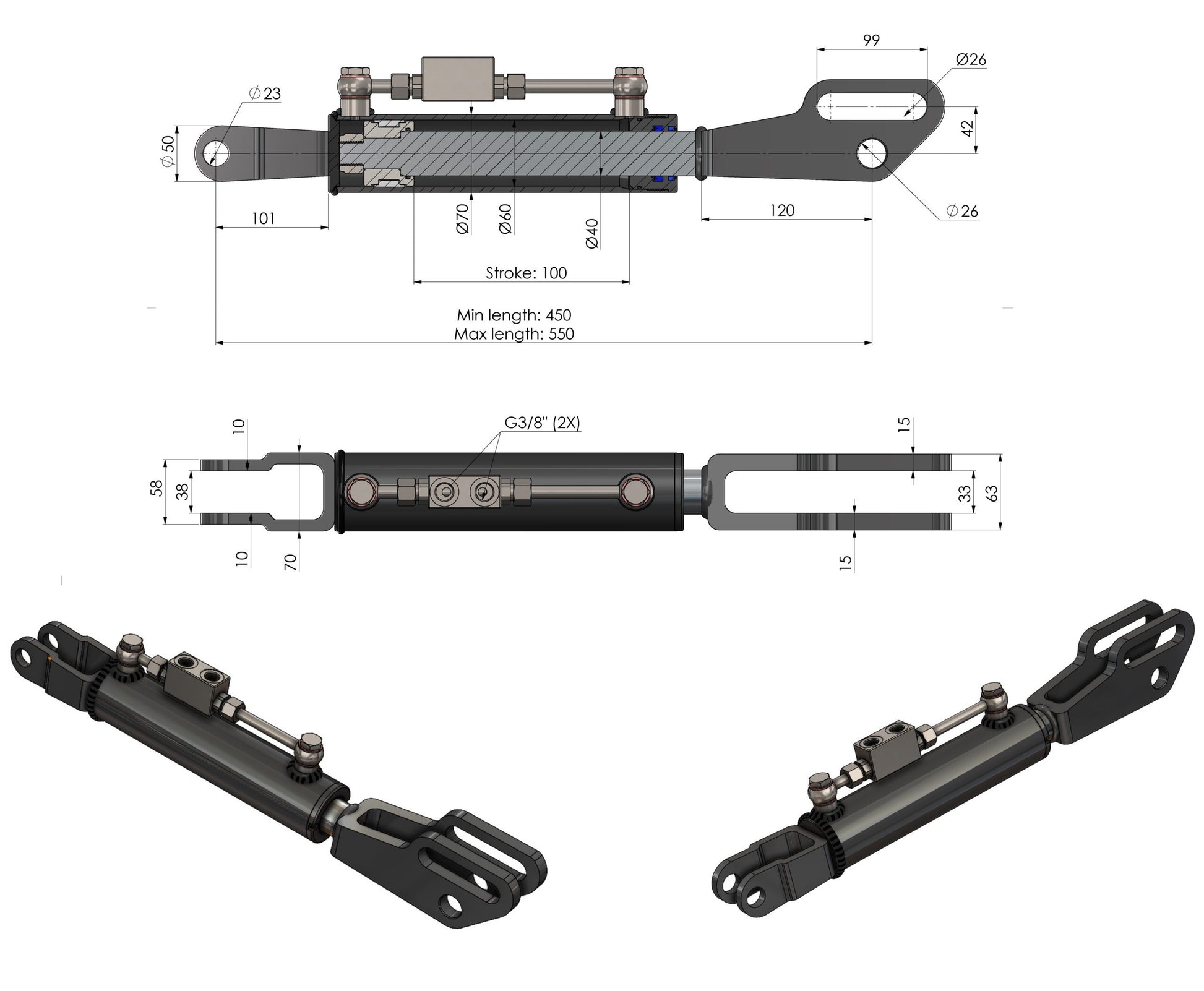
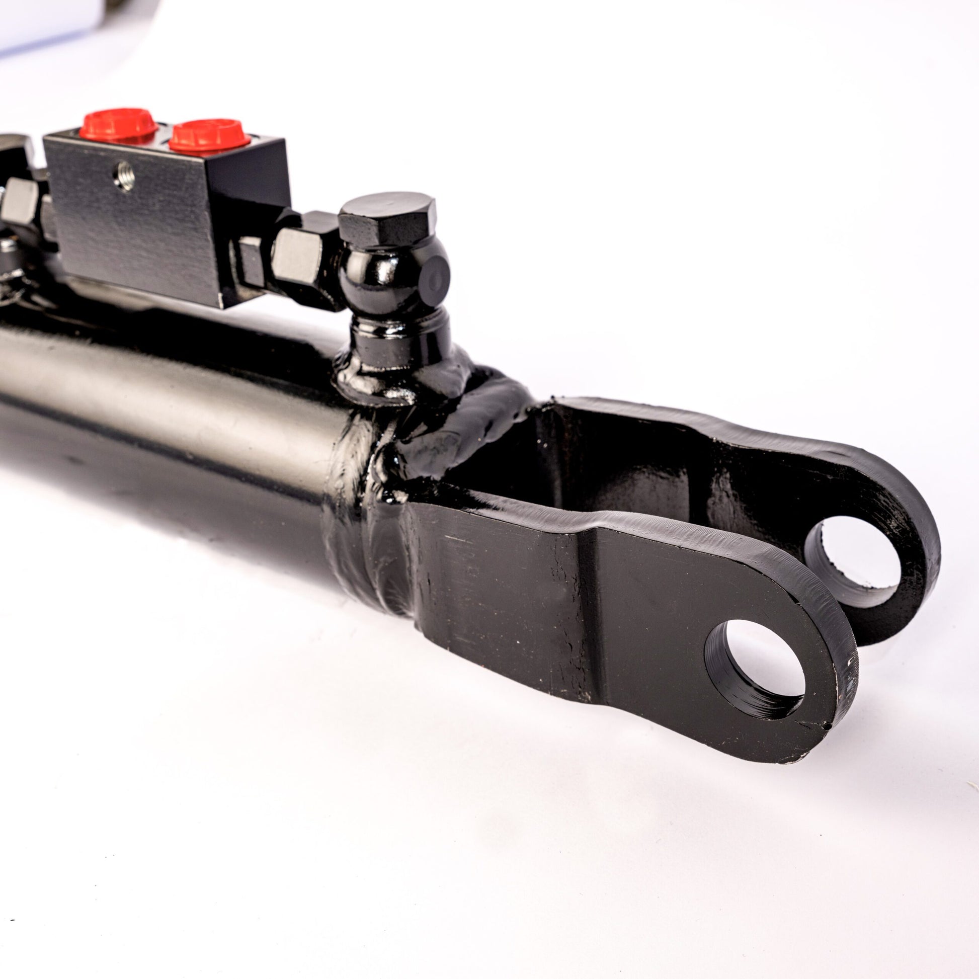
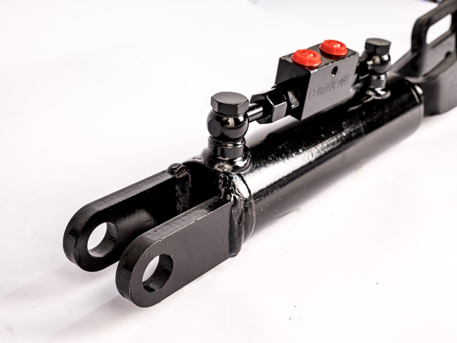
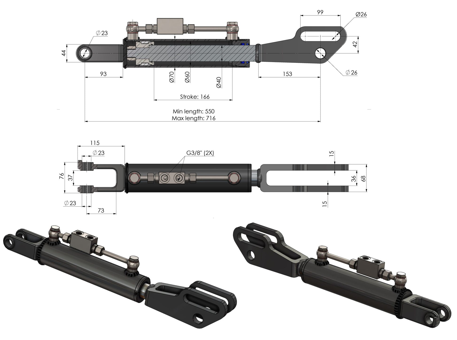
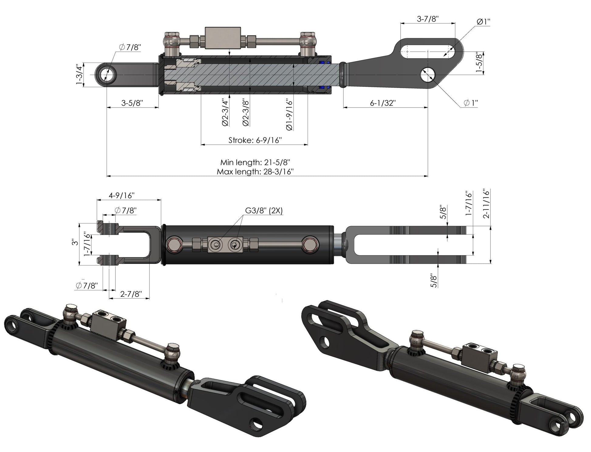
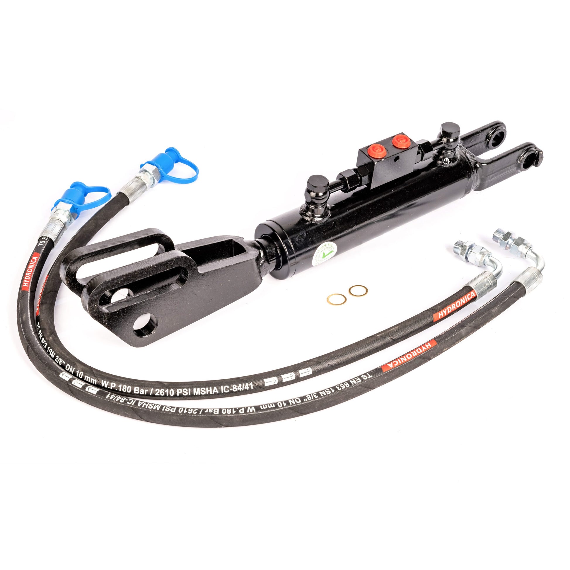
There are two end-fitting combinations. All six have a clevis with a round hole and a slot at one end. The other end has a ball joint or a second clevis. Use the product drawing to compare both mounting points with your tractor.
Ball joint + slotted clevis
Clevis + slotted clevis
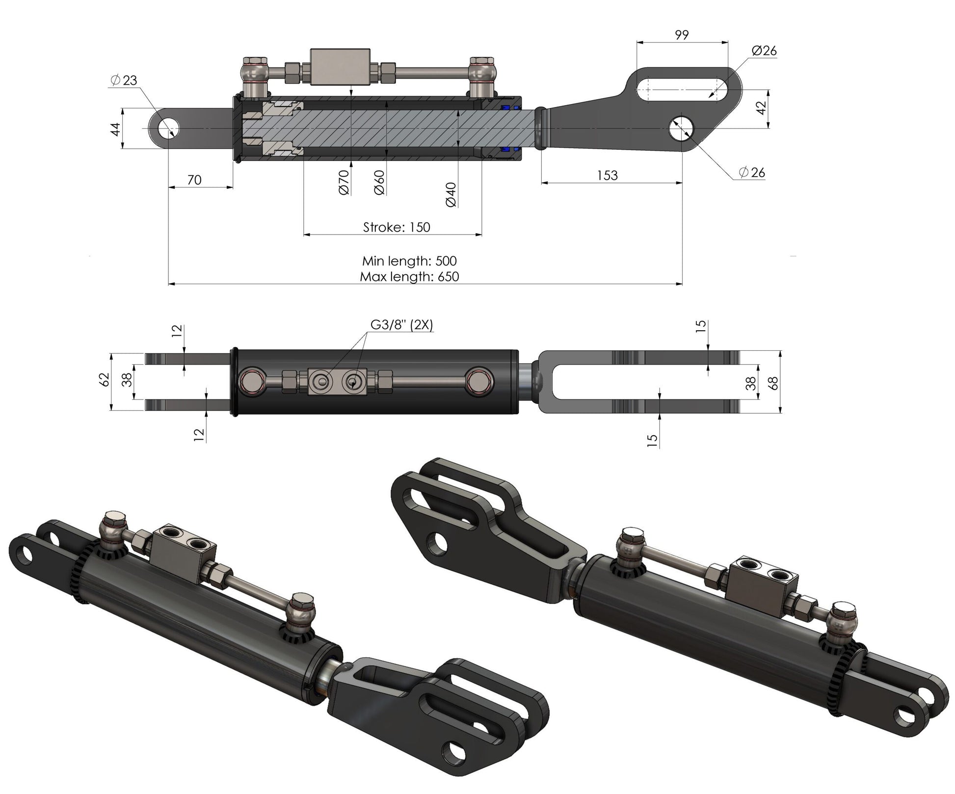
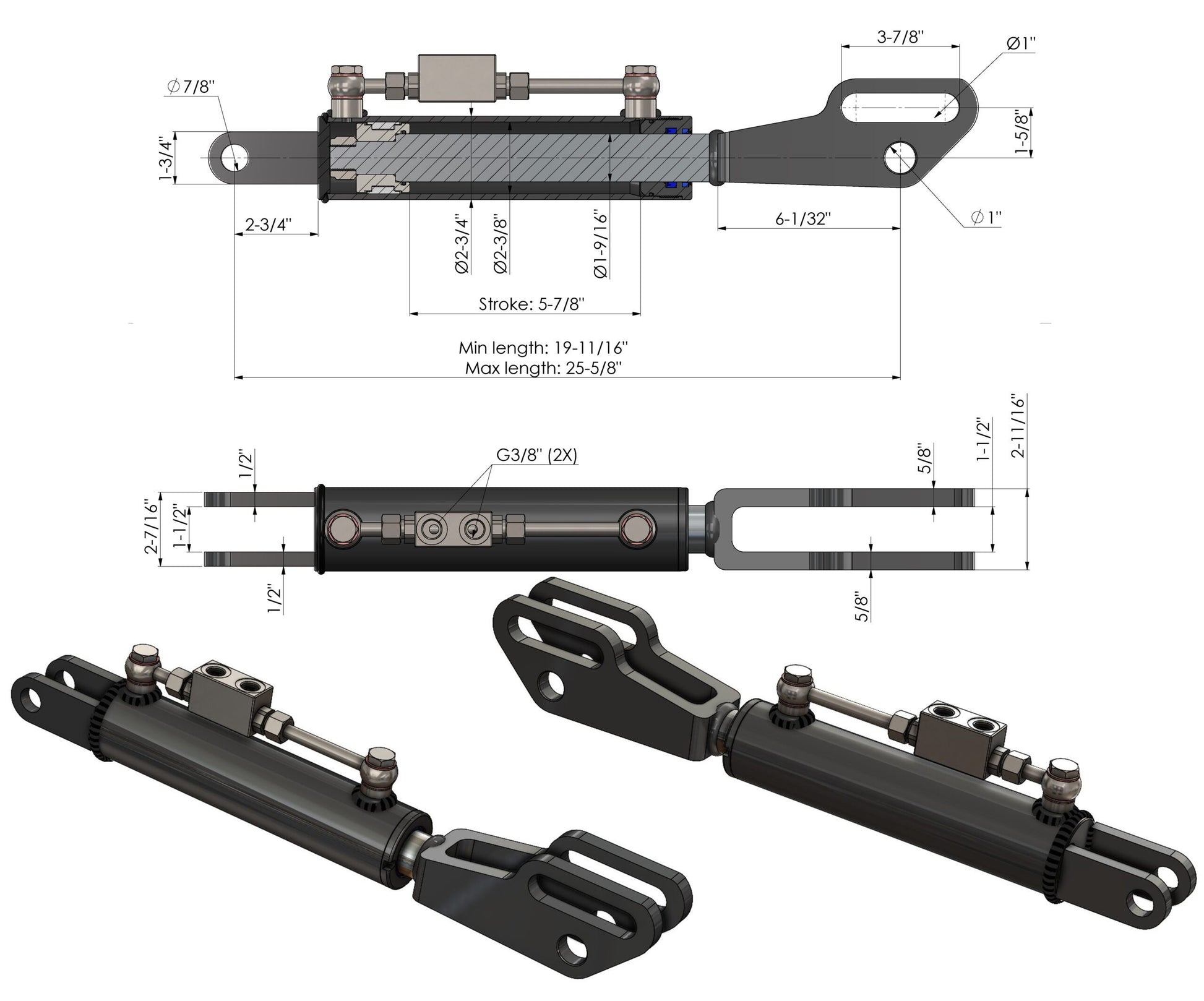
¹ Retracted–extended length according to the metric product drawing, measured between the indicated mounting points. Use the same measuring points when comparing. Open the product for all mounting dimensions and the scope of supply.
What does 60/40 mm mean?
All six drawings specify a 60 mm cylinder bore and a 40 mm piston rod: 60/40 mm. These are different from the cylinder’s outside diameter and the mounting-hole diameters. Cylinder size alone does not establish fit.
Check these dimensions before ordering
Compare your existing lift link with the selected product drawing. Check the shortest and longest required installation lengths, stroke and clearance throughout the linkage travel. Measure the mounting holes, ball-joint width or inside width of both clevises, and the positions of the round hole and slot.
Widths also differ within the same end-fitting group. SPH320107 and SPH320108 have different clevis dimensions. Do not select by length, tractor brand or category designation alone.
Hydraulic operation and connections
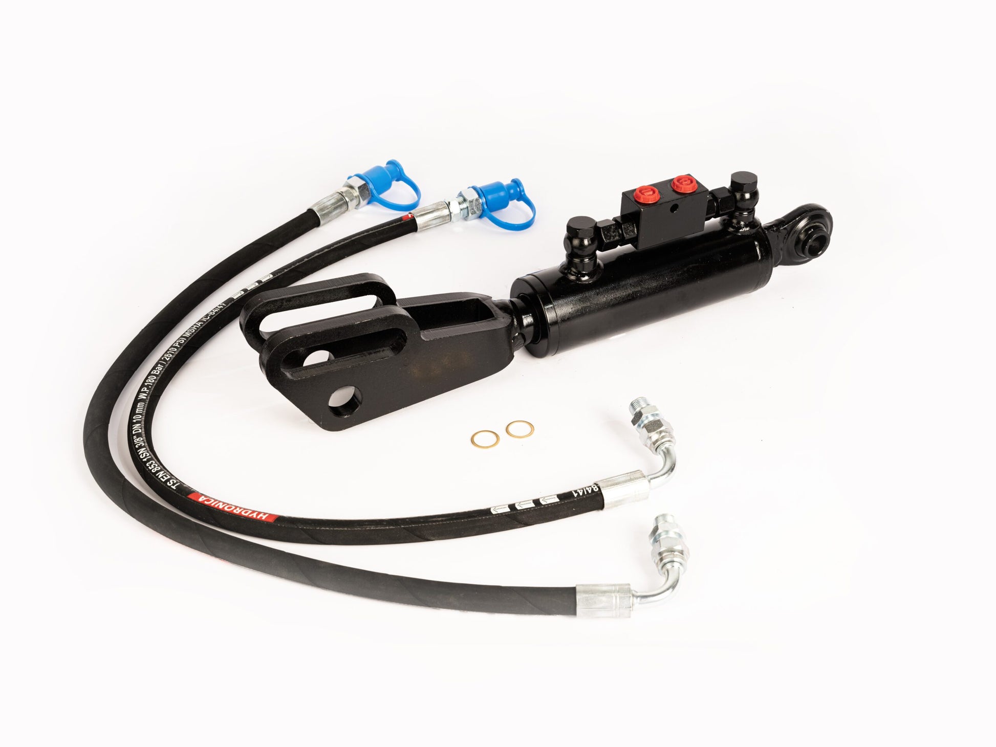
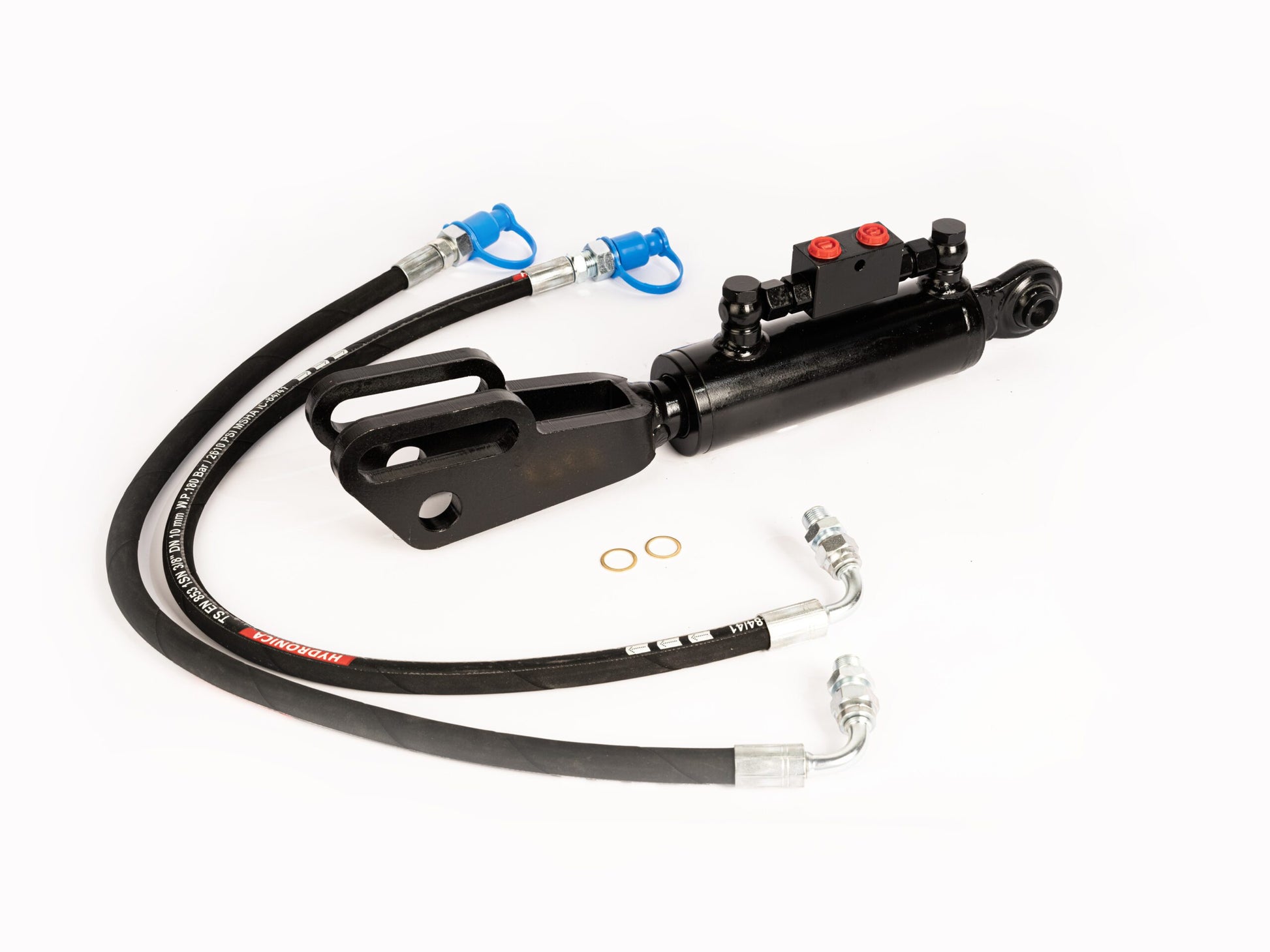
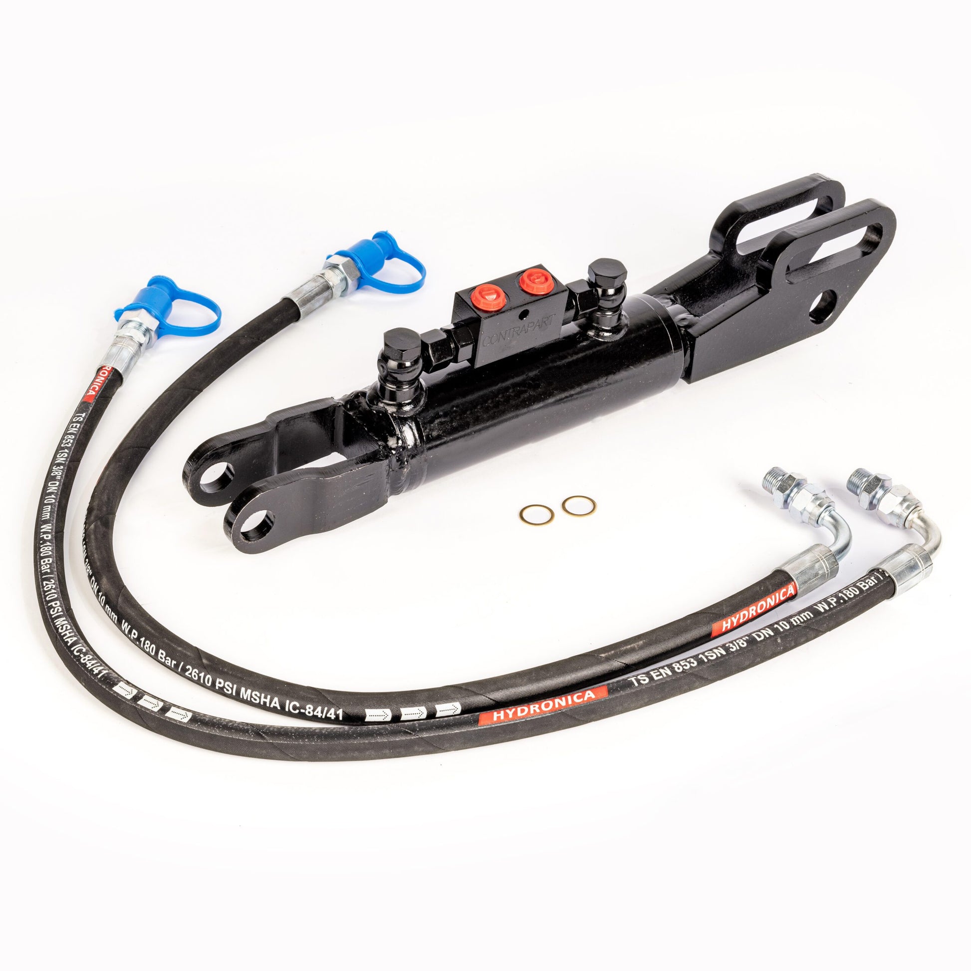
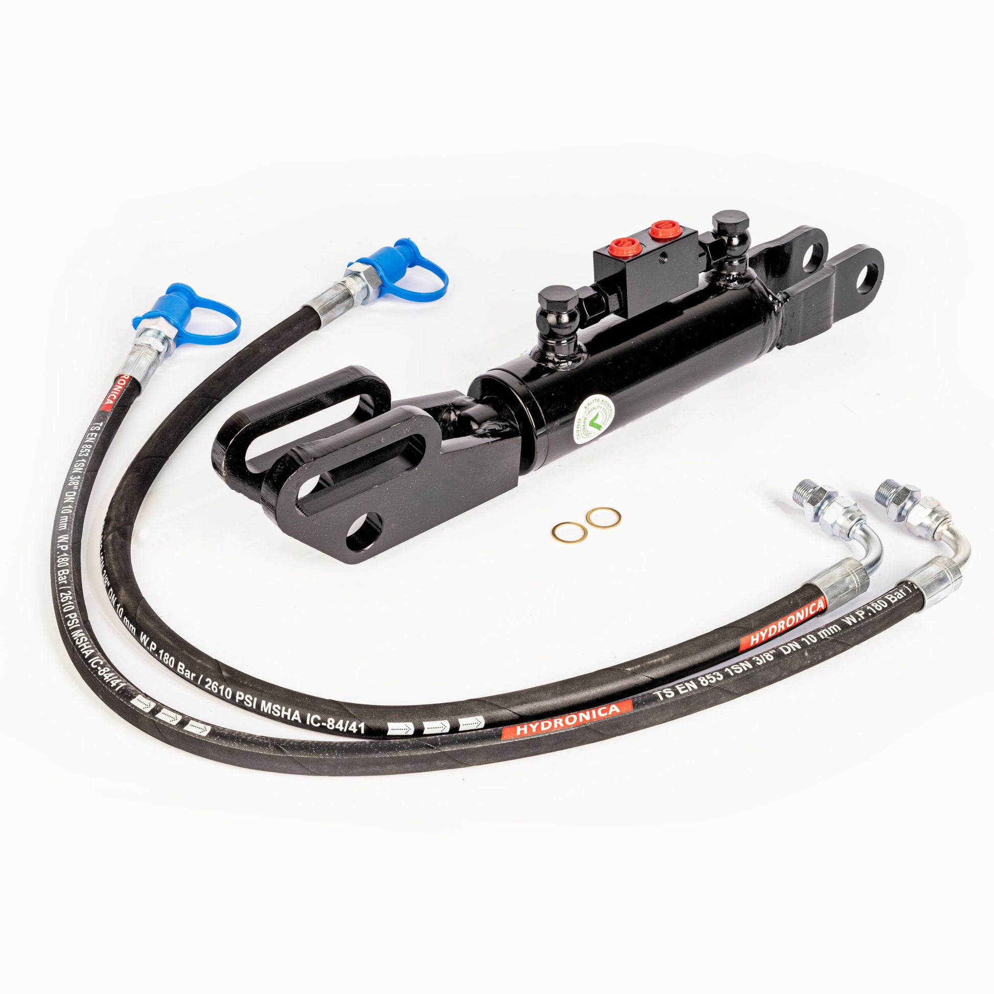
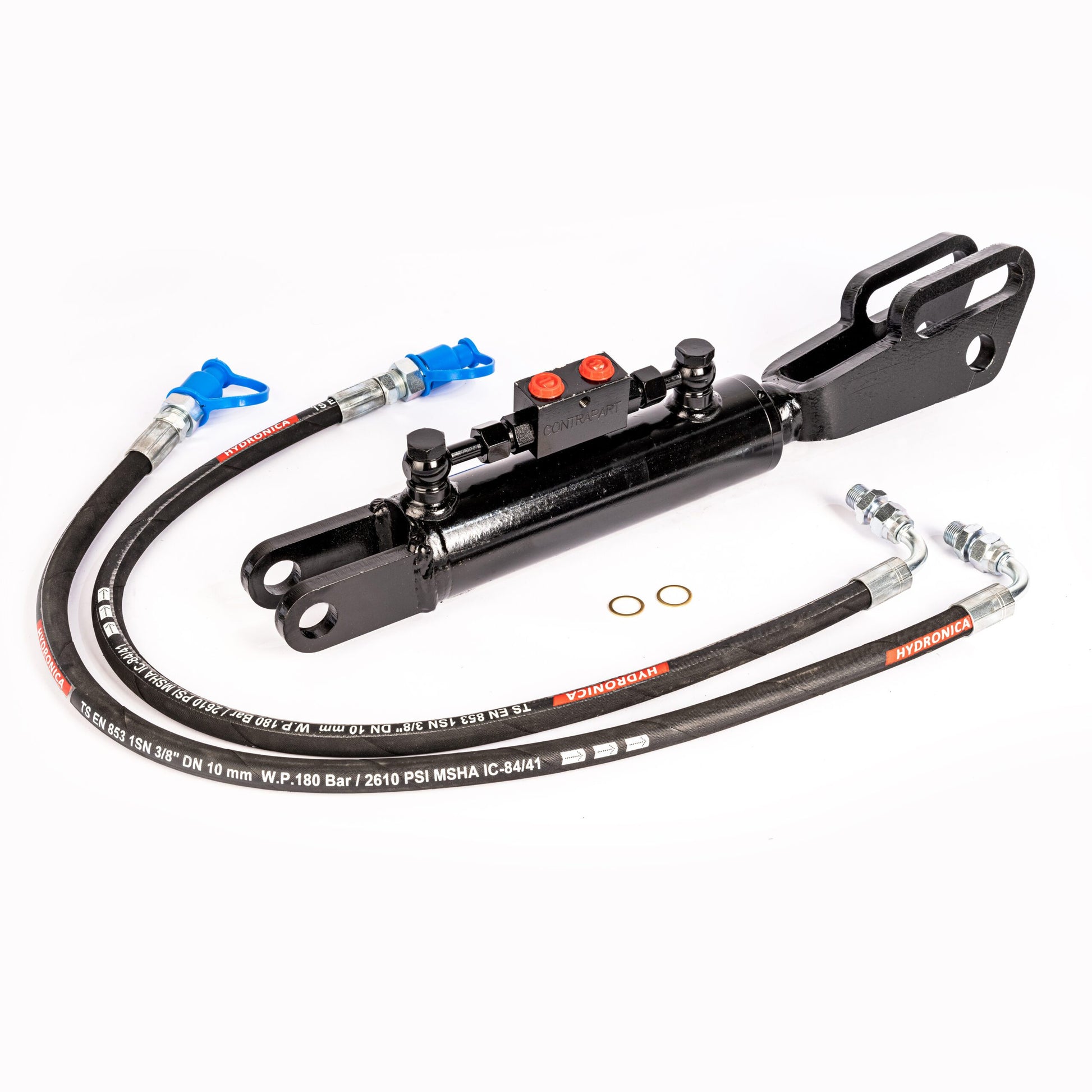
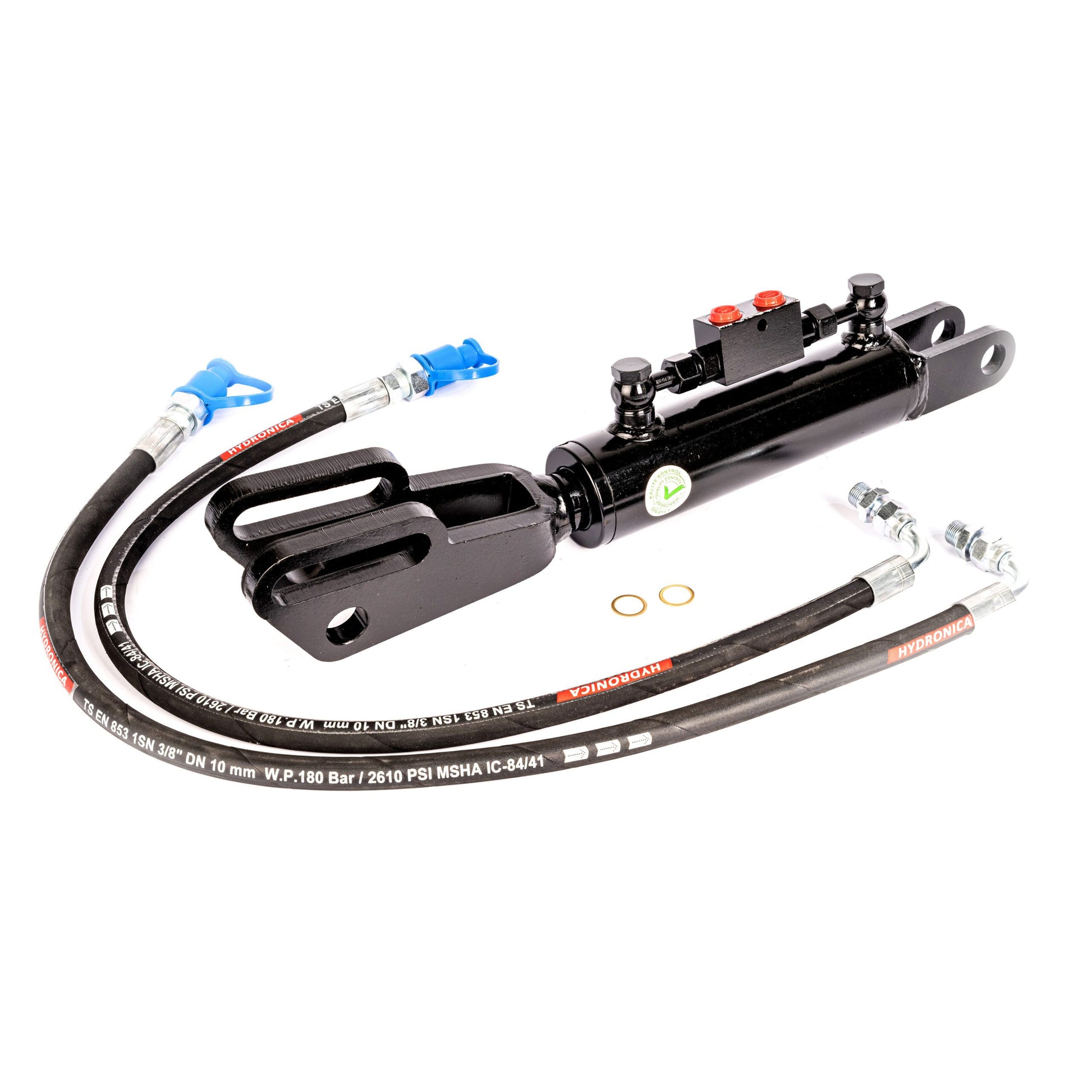
Check that your tractor has suitable double-acting hydraulic control. Compare hoses, couplings and the scope of supply on the product page. Allow for hose routing and clearance as the linkage moves.
The drawings show two G3/8″ cylinder ports. This thread designation does not identify the quick coupling required on your tractor. Check cylinder-side and tractor-side connections separately.
Lift link, top link or stabiliser?
A lift link connects a lift arm to a lower link; changing its length adjusts implement roll. A top link forms the upper connection to the implement and changes its fore-and-aft angle. A stabiliser limits sideways movement of the lower links.
Compare the relevant part and its mounting dimensions: mechanical lift links and levelling boxes · hydraulic top links
Frequently asked questions
Is a hydraulic lift link the same as a hydraulic top link?
No. A lift link adjusts the height of one lower link and the implement’s side-to-side tilt. A top link is the upper connection and changes the fore-and-aft angle.
Will every lift link with the same length range fit?
No. End fittings, hole diameters, clevis widths and installation clearance must also match. Use the full drawing even if length and stroke are the same.
Should I choose a ball joint or a clevis?
Compare both mounting points of your existing lift link with the drawing. Choose the connection that matches the tractor’s construction and dimensions; the tractor brand alone does not confirm fit.
What should I check at the slot?
Compare the position, length and width of the slot and round hole with the existing mounting. Follow the tractor or linkage instructions for the correct mounting position. Have uncertain fitment checked first.
Need help choosing a lift link?
Send your tractor model, photos of both mounting points and the measured dimensions of your existing lift link via WhatsApp. Include the product code you are considering.
Send your photos via WhatsApp